ECUTalk Resistor Modification for MicroSD support
This modification is required only for users with displays sent out before September
3, 2008 (I've done the modification for displays after this date). If you are not
sure, send me an email and I'll let you know if yours has the mod already or not.
If you are certain you won't want to use the MicroSD slot in the future for data
logging, then you dont need the modification either. This guide has been compiled
by a user of the display and reproduced with permission.
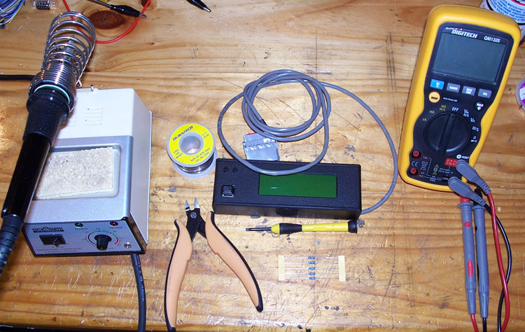
The Tools:
1 Soldering iron
1 Spool of solder
1 47 Ohm 1/2 watt resistor
1 Small flat blade screw driver
1 Pair of mini side cutters
(optional)
1 Multimeter
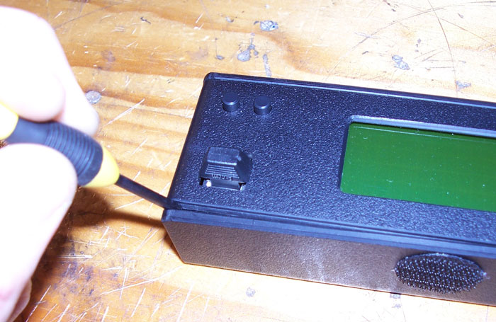
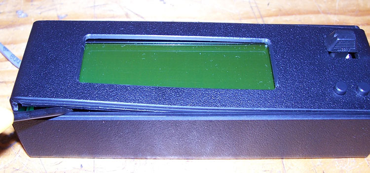
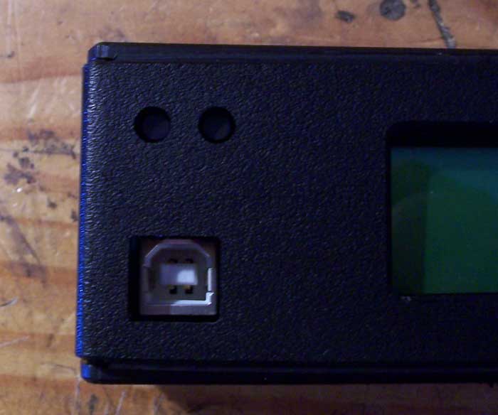
Step 1: Removing the casing
There is no glue, and there are no screws holding it together. Its a cleverly designed
interlocking channels keep it in place.
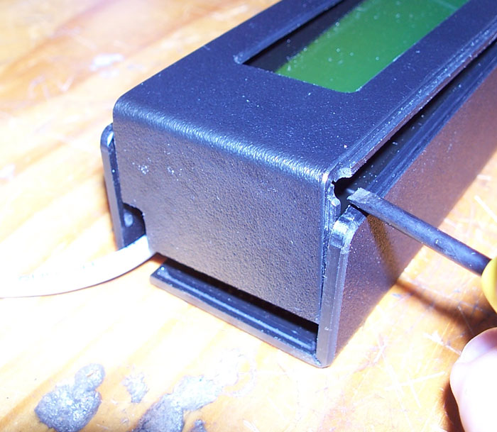
I didn't take the USB plug out yet, but at this point i would suggest you do.
Using the small flat blade screwdriver, pry at one corner to reveal the slot. Using
the screw driver at an angle, you can open the edge up and slide the screw driver
across. During this process go slowly and use your fingernail to "help" the casing
open to avoid damage to the male edge of the slot.
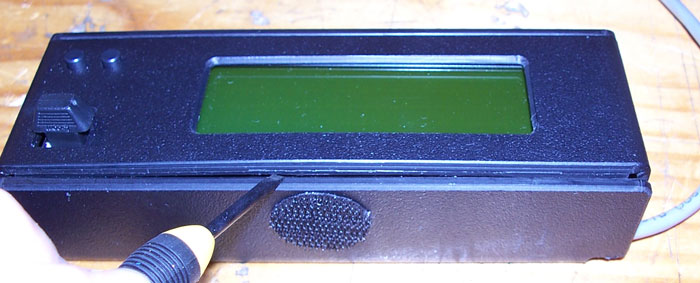
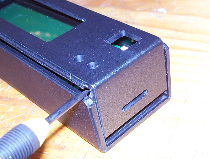
Once its been freed the whole way across, do the same on the other side.
At this point the casing will now be loose at the top, but still engaged in the
side slots. Again using the same technique, lightly pry at one corner and lift the
top up and it will start to come free.
Do the same on the other side and the casing will come off.
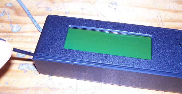
Now that the casing is off, you can remove the consult LCD display and set the casing
aside.
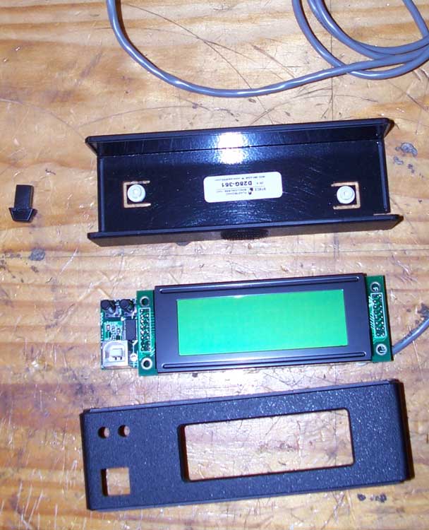
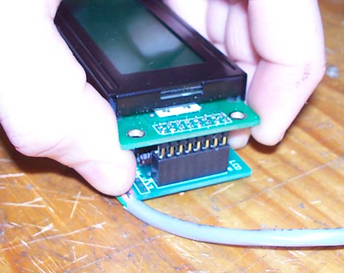
Step 2: Removing the LCD
Carefully and most importantly, evenly pull on each side edge of the LCD to pull
it from its connector. It shouldn't need much force but make sure you pull it upwards
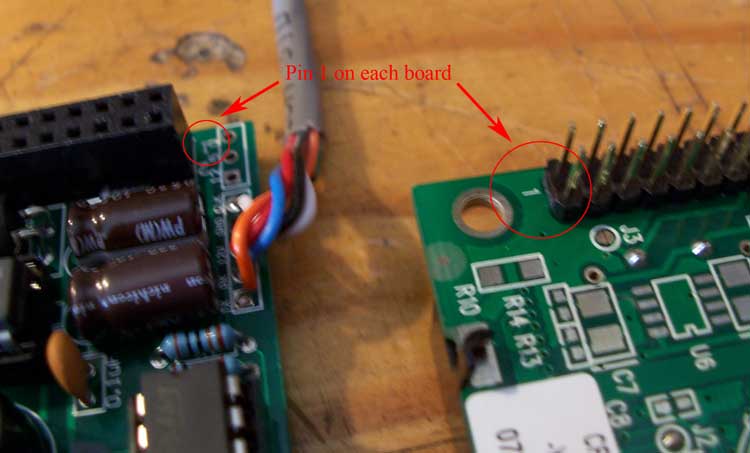
evenly so you don't bent any pins. At this point note the orientation of the LCD
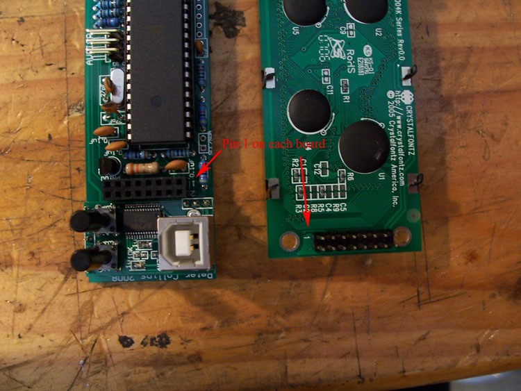
as it is possible to put it back on the board up-side-down, (but you won't be able
to close the case i'm told). If you lose track of which way up it was, just look
at the board and the LCD display pins and line up Pin 1 with Pin 1.
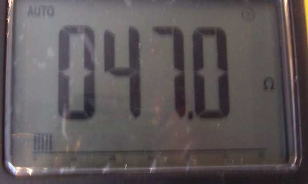
Step 3: Ready your resistor
I often test the resistor first, because like music, i just used to write the notes
rather than learning to read it, so i use my meter to check the resistor value (unless
i have bought it in an already labeled packet).
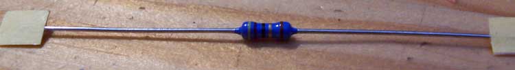
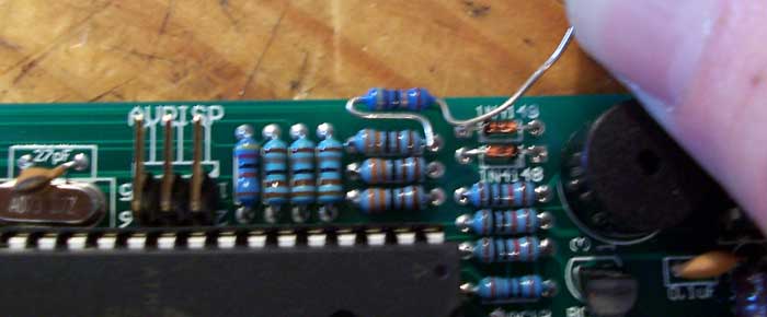
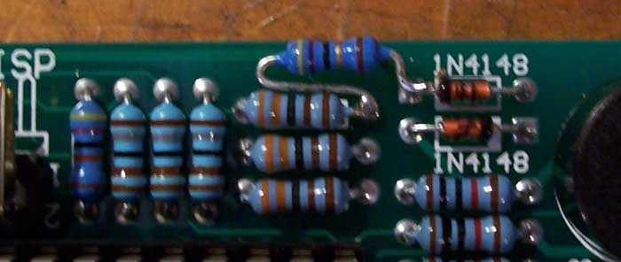
Bend the legs on the resistor into the shape you think will fit best in on the board.
In this case, the resistor can be connected to any of the 3 legs of the resistors
in the row, but MUST be connected to the specific point on the diode shown.
(Edit by Peter: I found placing the legs of the resistor 'under' the diode and other
resistor was the easiest method - you can then cut the legs etc before sliding it in
position and soldering.)
Step 4: Soldering
Optionally add a little extra solder to the 2 points you're going to solder the
resistor to, trim the leg on the resistor to the right length if you haven't and add
some solder it to it as well. Place the resistor in position and solder one leg down to
hold it in place. Then use the side cutters to trim the other leg and bend it to a final
position. Apply some heat and with the solder you've added to each component before
putting it in place you'll probably not even need to add more solder to the joint.
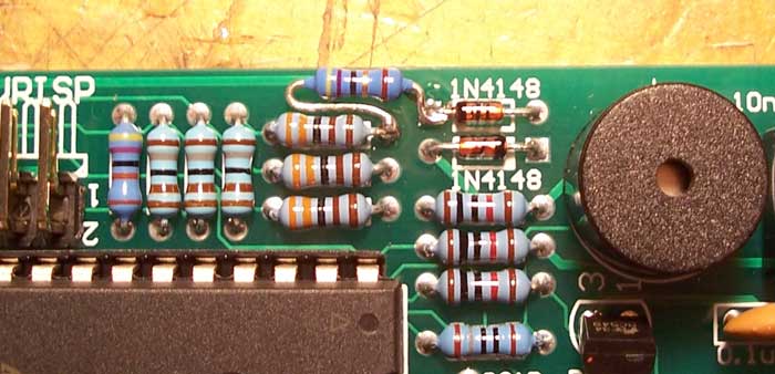
After you've checked the connection is solid and the resistor isn't going to go
walk about its time to re-assemble...
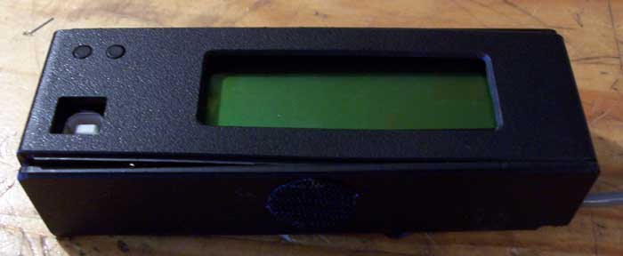
Step 5: Reassembly
Surprising, its the reverse of assembly..........
Again, you need to be careful with each step.
Line up the LCD and carefully push it into place. Try not to touch the display screen
if you can avoid it.
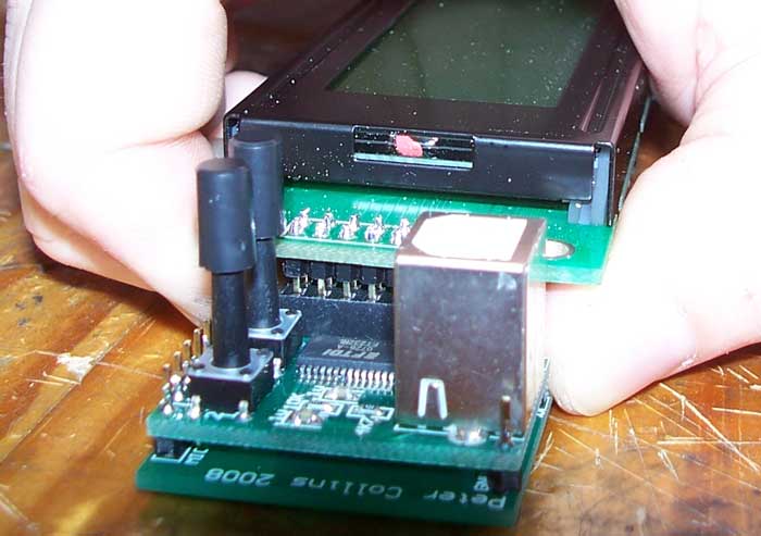
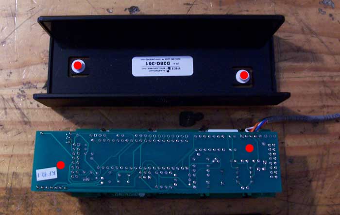
Next place the unit into the casing. Note here the small "stand offs" are positioned
specifically to push onto a flat part of the PCB, so make sure you have it up the
right way.
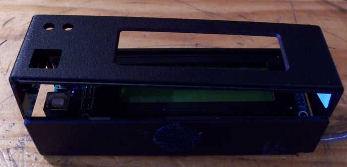
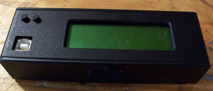
When putting the top cover back on, be gentle locking in the slots and pay close
attention to making sure the buttons line up with the 2 holes before you push it
down.
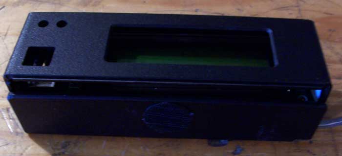
Using the screw driver pry one corner open so you can start to push the slot into
place. Just like taking it apart, once one edge is in you can push along the seam
and it will "click" into place. Do the same on the other side and you're done !!!!
If you've got this far, time to plug it in and make sure its still working, if so,
Well done !!! If not, refer to the start of this post.